By Pedro Costa Pinto (CERN)
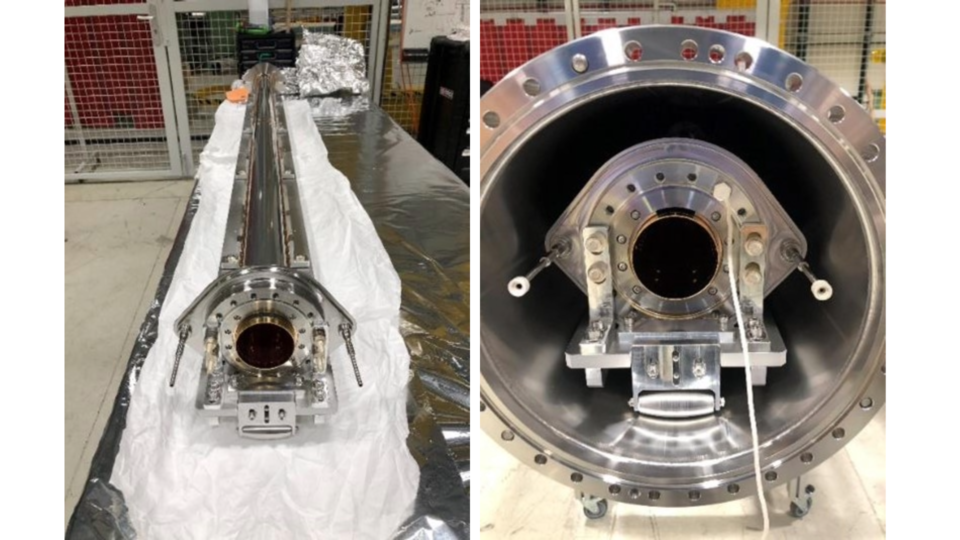
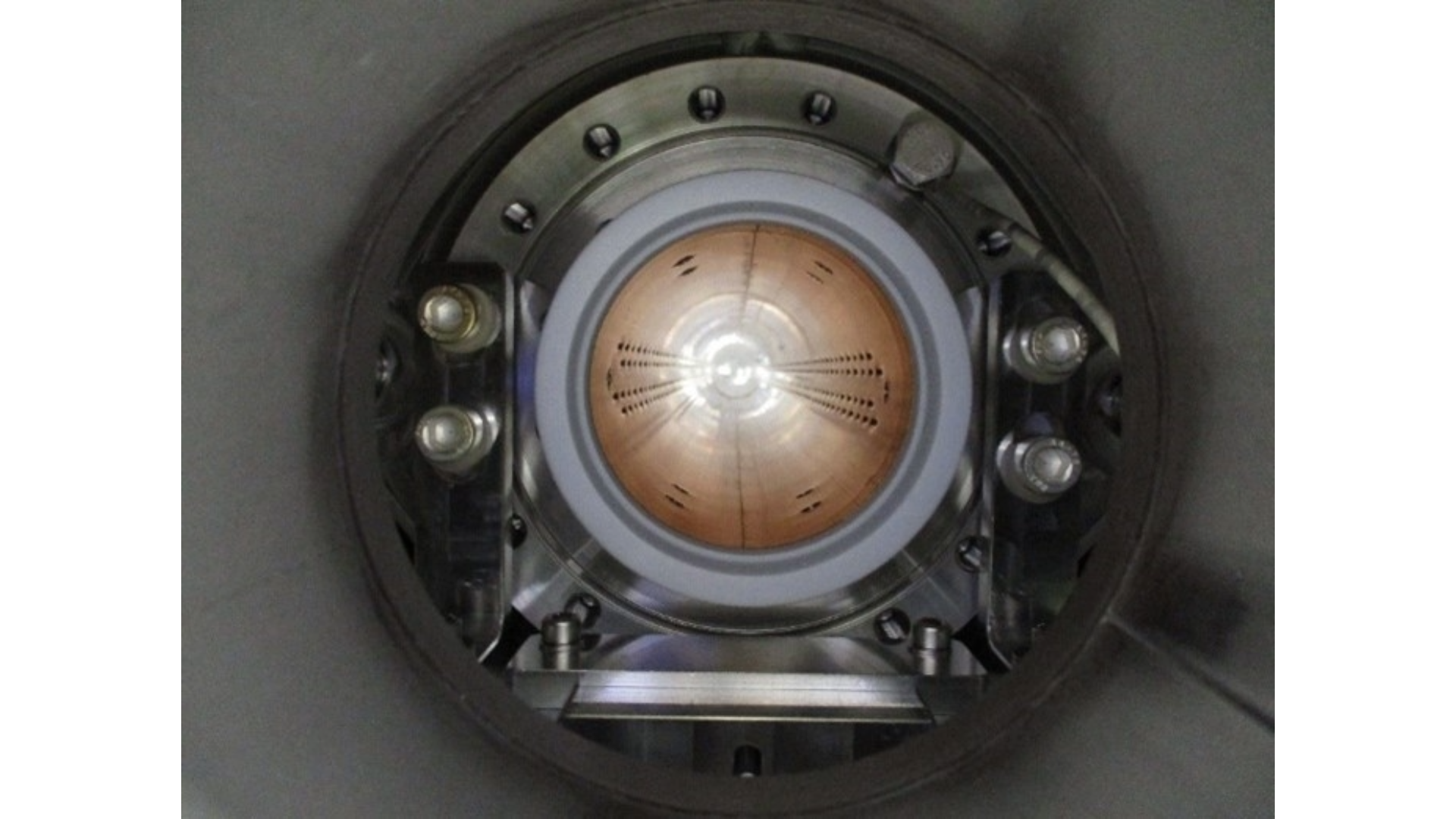
The non-crabbed line in the cryomodules for the HL-LHC crab cavities host a carbon-coated beam screen. This coating reduces the emission of secondary electrons from the beam screen surface, suppressing the formation of electron clouds that can result in the deterioration of the beam vacuum and heat loads to the cryogenic system.
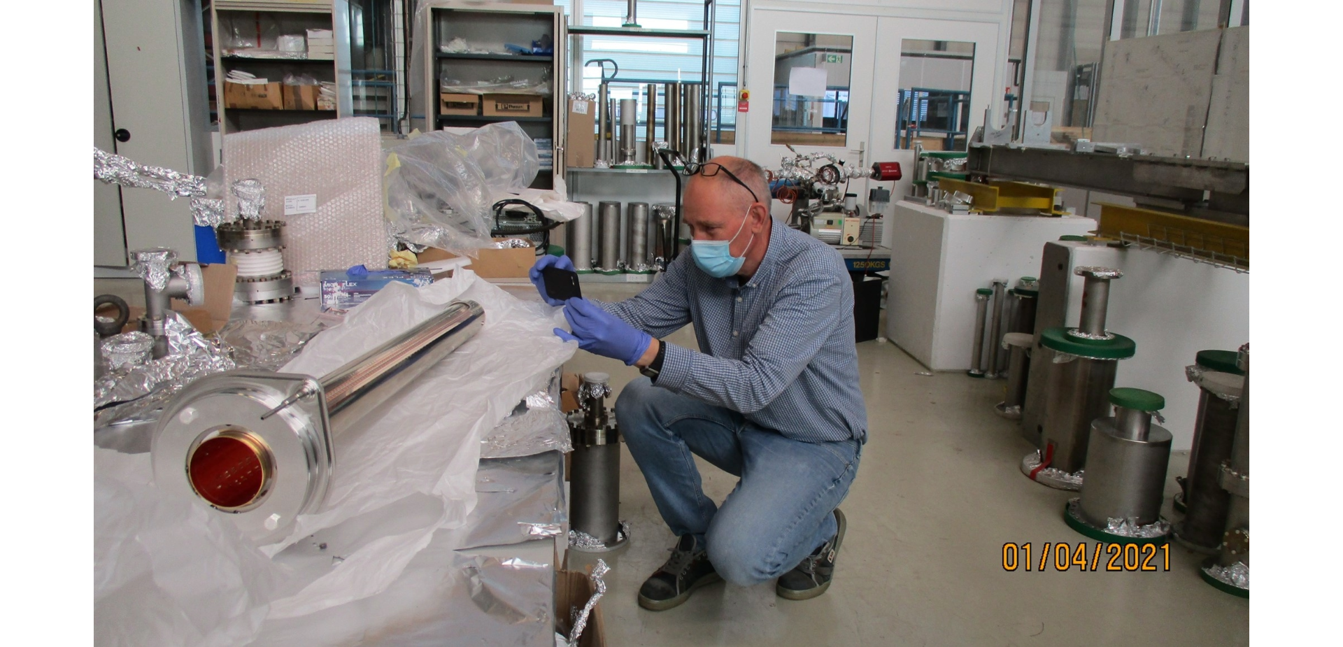
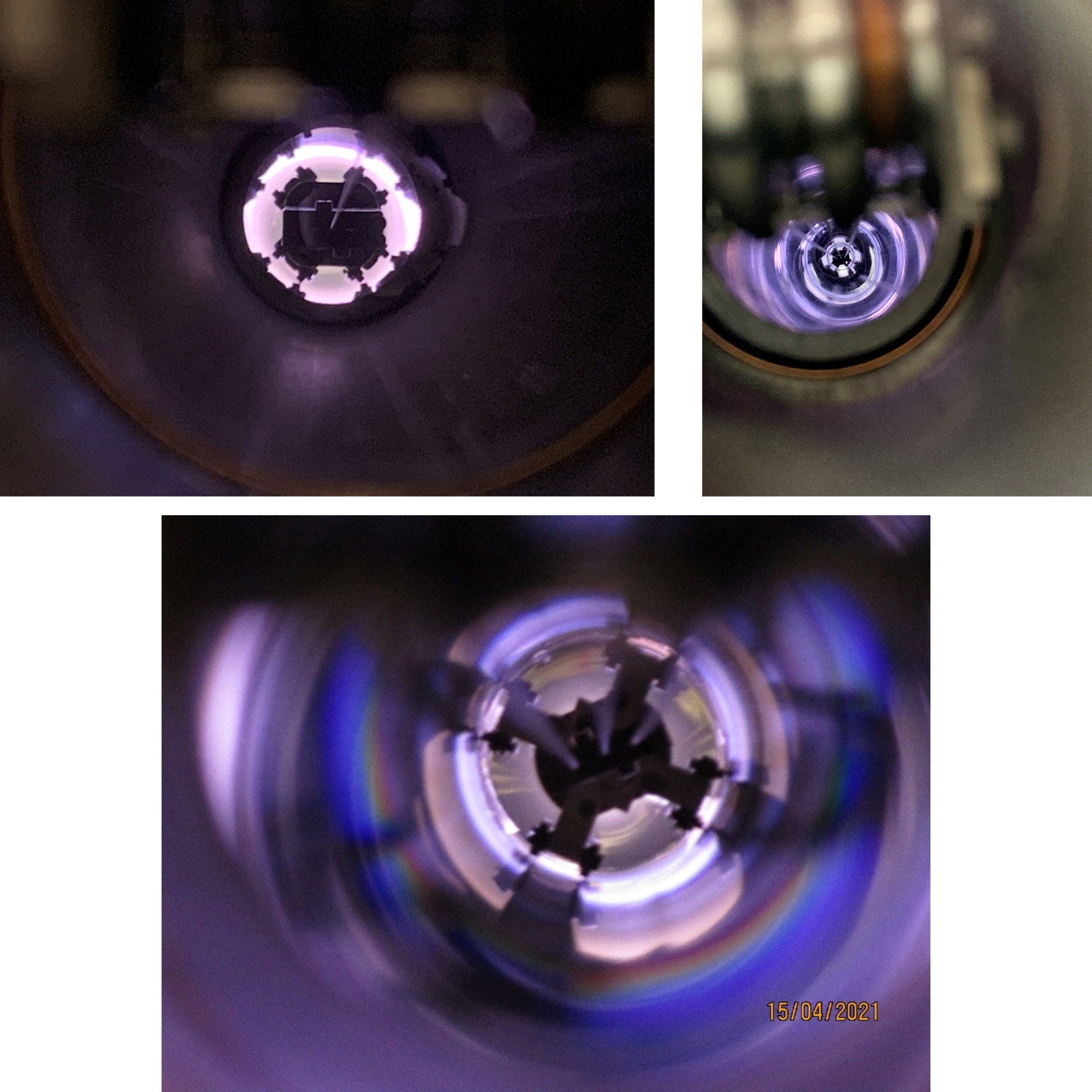
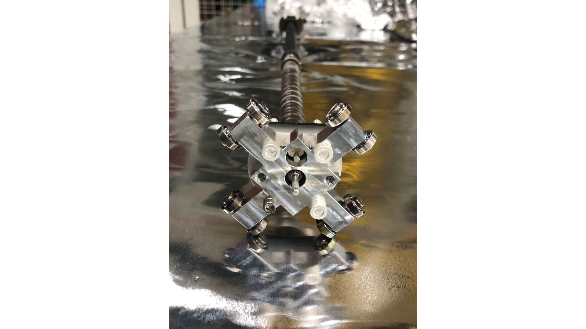
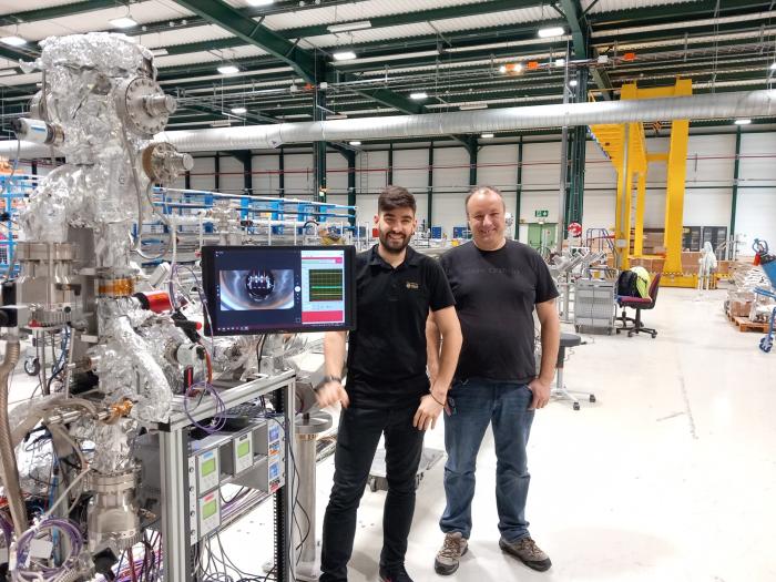
The coating is applied by sputtering, a physical vapor deposition technique that consists of bombarding a graphite target with argon ions with an energy of approximately 400 eV, ejecting carbon atoms from the target that condense on the inner walls of the beam screen, forming a thin film with a thickness of 100 nanometres. The whole process occurs in a rarified argon atmosphere, where the argon ions are formed by electron impact in a glow discharge. These ionising electrons are confined in the vicinity of the graphite target by a magnetic field produced by small permanent magnets. The target with the magnetic circuit is pulled by cables along the entire length of the beam screens, to cover all the surfaces facing the beam of protons in the HL-LHC. “The whole system was conceived, designed, and constructed at CERN”, says Spyridon Fiotakis, responsible for the design and fabrication of the coating setup. “We cannot buy these systems, it simply doesn’t exist on the market.”
As the performance of these anti electron cloud carbon films is strongly affected by the incorporation of impurities, the quality of vacuum during the deposition process is crucial. This necessitated a careful choice of materials, thermal treatments, and a differential vacuum between the chamber housing the spools with the cables for displacing and powering the targets, and the chamber where the deposition takes place.
To further reduce the amount of impurities, a second target simultaneously deposits a sublayer of titanium, (subsequently covered by the carbon film). “The titanium acts as a vacuum pump, removing hydrogen and water molecules from the vacuum system”, says Bernard Henrist, responsible for the coating process. “The control system, allowing remote monitoring and operation, was also conceived and constructed at CERN, by the BE-CEM group.”
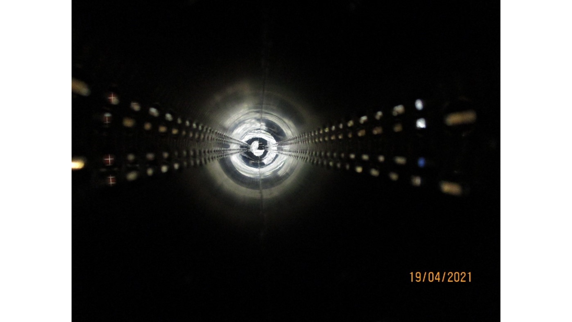
A total of 13 runs was necessary to coat the 26 beam screens (14 RFD type and 12 DQW type, including 2 spares for each type). The emission of secondary electrons was measured in witness samples and, for all the runs, remained below the threshold for electron multipacting. The beam screens are stored and ready for installation in the cryomodules for the crab cavities.
“However, the carbon coatings for HiLumi are not finished. We are now converting the two production systems in SMA18 to coat the beam screens for the new inner triplets for the LHC. The production will start before the end of 2024”, say Henrist and Fiotakis.
Related photo collection here.
